
Cathode Ray Tube (CRT)
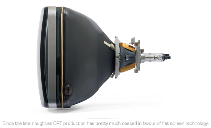
The original CRT - Cathode Ray Tube
The cathode ray tube (CRT) is a vacuum tube containing an electron gun (a source of electrons) and a fluorescent screen, with internal or external means to accelerate and deflect the electron beam, used to create images in the form of light emitted from the fluorescent screen. The image may represent electrical waveforms (oscilloscope), pictures (television, computer monitor), radar targets and others.
CRT Basics - How does it work: A cathode ray tube (CRT) uses an electron gun to shoot electron beams through a metal grille or mask on the inside of a glass monitor screen. The screen is coated with phosphor dots that glow red, green, or blue as the electron beam hits them, combining the three individual colours to create any colour or image. Shooting the gun at the appropriate colours in differing intensities produces the full colour spectrum.
CRT screen size is based on the diagonal screen measurement of its picture tube which is usually an inch larger than its viewable image size. A 17" CRT, for example, typically has a 16" viewable image size, with the edge of the picture tube covered by the bezel of the monitor.
Dot Pitch is the spacing between pixels on a CRT, measured in millimetres. Generally, the lower the number, the more detailed the image.
Resolution of a CRT screen is made up of individual dots of colour, or pixels. Resolution refers to the number of pixels contained on a display. Resolution is typically expressed by identifying the number of pixels on the horizontal axis (rows) and the number of lines on the vertical axis (columns), such as 720x576 for PAL Standard Definition (SD) or 1920x1080 for High Definition (HD).
Refresh Rate is the number of times per second that a CRT's picture must be redrawn. The standard rate is 50Hz but increasing this to 100Hz or better still 200Hz will avoid flicker and cause less strain to the viewers eyes.
LCD - Liquid Crystal Display
LCD Basics - How does it work: LCD (liquid crystal display) monitors use liquid crystal filled grids, activated by electric fields, to create smooth, finely detailed images. The liquid crystal acts like a shutter that either blocks the backlight or lets it pass through to light up a particular colour filter. The screen has hundreds of thousands of pixels that are charged or not charged, making them reflect or not reflect light to form images. LCD technology produces the same image as a CRT, but in a much smaller package. Different types of LCD technology use different alignment modes to filter or twist incoming light, with differing results.
Resolution: an LCD screen is made up of individual dots of colour, or pixels. Resolution refers to the number of pixels contained on a display. Resolution is typically expressed by identifying the number of pixels on the horizontal axis (rows) and the number of lines on the vertical axis (columns), such as 1920 x 1200 (1920 x 1080 active video area).
Brightness: LCD brightness is calculated by measuring the greatest amount of light that comes from the screen when displaying pure white. The measure is expressed in candelas per square metre.
Contrast Ratio: refers to the difference in light intensity between the brightest white and the darkest black that an LCD can produce. Higher contrast ratios help prevent colours from washing out when you turn up the brightness and from disappearing when you turn it down.
Colour Depth: indicates how many colours can be displayed on a monitor's screen. Colour depth is usually talked about in bits, describing how many bits are used for each of the three additive primary colours - red, green and blue - per pixel. So, for example, if 8 bits are dedicated to each of the three colours, the colour depth is 24-bit (8 bits x 3 colours = 24).
Pixel Pitch: is the spacing between pixels on an LCD, measured in millimetres. Generally, the lower the number, the more detailed the image.
Viewing Angle: because of the way light passes through the liquid crystals in the display, LCDs appear to lose brightness and image quality as you move to the side of the screen, or above or below it. An LCD's viewing angle indicates how far, in degrees, you can move from the centre of the display before the image quality deteriorates to unacceptable levels. A wider viewing angle indicates more freedom to view the monitor from the side, from above or below the screen position.
Refresh Rate: is he number of times per second in which the monitor draws the data it is being given. A refresh rate that is too low can cause flickering and will be more noticeable on larger monitors. Many high-end LCD televisions now have a 120Hz (current and former NTSC countries) or 200Hz (PAL/SECAM countries) refresh rate. The rate of 120 was chosen as the least common multiple of 24 fps (cinema) and 30 fps (NTSC TV), and allows for less distortion when movies are viewed due to the elimination of telecine (3:2 pulldown). For PAL/SECAM at 25 fps, 200Hz is used as a compromise of one-third the least common multiple of 600 (24 x 25). This is most effective from a 24p-source video output (available on Blu-ray DVD).
Dead Pixels: these can occur when the screen is damaged or pressure is put upon the screen. Top end manufacturers only pick the best displays available and should replace screens with dead pixels under warranty.
In LCD manufacture, it is common for a display to be manufactured that has a number of sub-pixel defects (each pixel is composed of three primary coloured sub-pixels). The number of faulty pixels tolerated before a screen is rejected is dependent on the class that the manufacturer has given the display. Some manufacturers have a zero tolerance policy with regard to LCD screens, rejecting all units found to have any pixel defects obviously these are more expensive.
LED: an LED screen is actually an LCD screen but instead of having a normal cold cathod fluorocent light (CCFL) backlight, it uses light emitting diodes (LED) because an LED is more energy efficient & also enables thinner television screens to be manufactured. LED TVs are still LCD TVs because the screens themselves are comprised of liquid crystals.
What goes on inside your LCD screen? (Courtesy of Samsung Display)
Let us ride on a beam of light as it passes through the various components of an LCD screen:
LCD components deconstructed

Bottom Chassis: Bottom chassis protects the LCD display components and acts as a foundation that houses the components together.
Backlight: Liquid crystals do not generate light of their own, so another means of providing light is required to allow the screen to be viewed. The light source can either be an ambient light or an artificial light source located behind or to the side of the screen. An LCD is a transmissive display, thus it needs an external light source.
An LED-backlit LCD display is a flat panel display that uses LED backlighting. The use of LED backlighting allows for a thinner panel, lower power consumption, better heat dissipation, a brighter display, and better contrast levels. Light emitting diodes (LED) provide light for the display. The most common backlight arrangement these days is is either Edge LED (slimmer profile) or Direct LED (for high-brightness displays or narrow bezel video wall displays). The design of the backlight is important to ensure good color reproduction and a broad color gamut. Just because a backlight looks white, doesn't mean that it has a broad and even spectrum—it might have a very irregular "peaky" spectrum (and CCFL lights usually do).
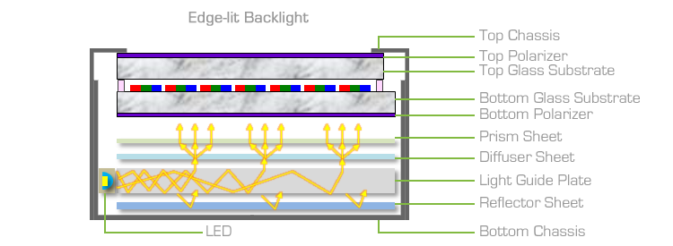
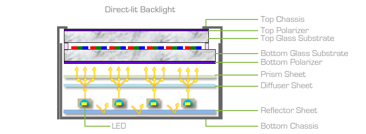
Reflector Sheet: A reflector sheet provides LCD backlight recycling. It is often called DBEF (dual brightness enhancement film). DBEF increases on-axis luminance and thus more light is available to be transmitted through the LCD. Typically, one BEF can increase brightness by 40%-60%. In some applications, two BEFs are used for enhanced brightness transmittance.
Light Guide Plate (LGP): LGP is an acrylic panel typically made from pure PMMA (poly methyl methacrylate) resin. PMMA is extremely transparent and highly weather resistant. The light guide is a sheet of plastic etched with a pattern of bumps that reflects light in a particular direction. LGP converts a line-shaped light source into a uniform plane-shaped light source. A matrix of lines is etched on the bottom of the LPG panel to direct the light out the front, which is called V-cutting. Light entering the light guide layer from the sides will exit through the front.
Diffuser Sheet: A diffuser sheet is designed to break up and distribute light evenly to give the soft light. The diffuser sheet spreads the light evenly across the screen dimensions making a solid, evenly lit square and reduces LED hot-spots.
Prism Sheet: A prism sheet is provided on the upper surface of the light guide plate of the liquid crystal display. The prism sheet has small, angled ridges on its front-facing surface that recycle off-axis light until it is emitted at the optimal viewing angle. The light waves either exit at the brightest angle to the viewer, or they are sent through the back lighting layers again until they exit correctly.
Bottom Polarizer: Polarizer is made by stretching a plastic-like material to lengthen its fibers, then dipping the material in iodine to further lengthen and organize the material’s fibers into a grid of darkened parallel lines that are invisible to the human eye. This is like a filter that only allows light waves in a vertical orientation to pass through, and rest of the light waves are blocked off.
Bottom Glass Substrate (Backplane): Special glass used as a starting substrate for the thin film transistor (TFT) manufacturing process. The liquid crystal is normally 'sandwiched' between two polarizing filters at 90 degrees to each other. Polarized light enters the back of the liquid crystal from the back-lit LED. When the nematic crystal is not energized, it 'twists' the polarized light by 90 degrees so that it passes through the second polarizing filter. When an electric field is applied to the liquid crystal, the light does not get twisted so gets blocked by the second polarizing filter.
Thin Film Transistor: A transistor whose active, current-carrying layer is a thin film (usually a film of silicon—Si), in contrast to MOSFETs, which are made on silicon wafers and use the bulk-silicon as the active layer. In a flat-panel display, light must be able to pass through the substrate material to reach the viewer. Opaque silicon wafers obviously will not be suitable for these transmissive displays. Glass is the most commonly used starting substrate because it is highly transparent and is compatible with conventional semiconductor processing steps. Since glass is not a semiconductor like silicon, a thin film of silicon is deposited on top and the transistors are fabricated using this thin layer. TFT help manipulate the voltage at each subpixel to orchestrate the display image.
Liquid Crystal: Liquid crystals change orientation under an applied electric field and can thereby block or pass light. Liquid crystals are rod-shaped molecules that twist when an electric current is applied to them. Each crystal acts like a shutter, either allowing light to pass through or blocking the light. The pattern of transparent and dark crystals forms the image. The liquid crystals in an LCD display are in a naturally twisted form.
Common Electrode: It is made from the transparent indium-tin-oxide (ITO) for applying the voltage to liquid crystal layer. Common electrode plays a critical role in maintaining the uniform pixel voltage across the whole LCD screen. In color screens, the ITO is now separated into three colors: red, green, and blue (RGB).
Color Filter (RGB): Color filter creates colors for an image on LCD. The color filter is comprised of red, green, and blue pigment and is aligned with a particular subpixel within the cell. This filter is composed of the thin glass substrate and color resist. Three color resists (red, green, and blue) patterns are formed on the glass substrate. R, G, B patterns are called subpixels. An LCD that can show colors must have three subpixels with red, green and blue color filters to create each color pixel. Through the careful control and variation of the voltage applied, the intensity of each subpixel can range over 256 shades. Combining the subpixels produces a possible palette of 16.8 million colors (256 shades of red x 256 shades of green x 256 shades of blue with 8-bit color depth). These color displays take an enormous number of transistors (TFT’s). A typical laptop computer supports resolutions up to 1,920x1,080. If we multiply 1,920 columns by 1,080 rows by 3 subpixels, we get 6,220,800 transistors etched onto the backplane glass.
Top Glass Substrate: Special glass used for the color filter manufacturing process.
Top Polarizer: Light is horizontally polarized at the top polarizer. The function of the polarizer is to improve color and definition, making it possible to see the screens of LCDs. If polarizers were removed from LCDs, it would be impossible to recognize letters or graphics. When two polarizing films are placed one on the top of the other in parallel, the screen of the LCD will be at its brightest. However, when placed on the top of and perpendicular to each other, the screen will look as though it is black. Hence as described, the optical characteristics of LCDs, such as brightness and contrast, are greatly influenced by the properties of polarizing films.
Top Chassis or Frame: Top chassis is located on the top and use an open frame.
DLP - Projectors
Digital Light Processing (DLP) is a trademark owned by Texas Instruments, representing a technology used in projectors and video projectors. It was originally developed in 1987 by Dr. Larry Hornbeck of Texas Instruments. DLP is also one of the leading technologies used in digital cinema projection. Also because digital projection closely mirrors the theatre presentation, many feel more comfortable and trusting towards a full theatre presentation and screening. I have to say, by preference, I personally prefer to work in a dedicated theatre but not all facilities have the space.
DLP Basics - How does it work: Digital Micromirror Device - in DLP projectors, the image is created by microscopically small mirrors laid out in a matrix on a semiconductor chip, known as a Digital Micromirror Device (DMD). Each mirror represents one or more pixels in the projected image. The number of mirrors corresponds to the resolution of the projected image (often half as many mirrors as the advertised resolution due to wobulation). 800x600, 1024x768, 1280x720, and 1920x1080 (HDTV) matrices are some common DMD sizes. These mirrors can be repositioned rapidly to reflect light either through the lens or on to a heatsink (called a light dump in Barco terminology).
Rapidly toggling the mirror between these two orientations (essentially on and off) produces grayscales, controlled by the ratio of on time to off time.
Colour in DLP projection: there are two primary methods by which DLP projection systems create a colour image, those utilised by single-chip DLP projectors, and those used by three-chip projectors. A third method, sequential illumination by three coloured light emitting diodes, is being developed and is currently used in televisions manufactured by Samsung.
Single-chip projectors: in a projector with a single DLP chip, colours are either produced by placing a colour wheel between the lamp and the DLP chip or by using individual light sources to produce the primary colours, LEDs for example. The colour wheel is divided into multiple sectors: the primary colours: red, green, and blue, and in many cases secondary colours including cyan, magenta, yellow and white. The use of the secondary colours is part of the new colour performance system called BrilliantColor™ which processes the primary colours along with the secondary colours to create a broader spectrum of possible colour combinations on the screen.
The DLP chip is synchronised with the rotating motion of the colour wheel so that the green component is displayed on the DMD when the green section of the colour wheel is in front of the lamp. The same is true for the red, blue and other sections. The colours are thus displayed sequentially at a sufficiently high rate that the observer sees a composite "full colour" image. In early models, this was one rotation per frame. Now, most systems operate at up to 10x the frame rate.
Older DLP systems exhibit an anomaly known as the rainbow effect. While this has been improved with faster colour wheels over the years, some people will still be able to notice this effect. This is best described as brief flashes of perceived red, blue, and green observed most often when the projected content features bright/white objects on a mostly dark/black background (the scrolling end credits of many movies are a common example). Some people would perceive these rainbow artefacts frequently, while others may never see them at all. With the advent of increased colour wheel speeds or projectors featuring LED illumination, the 'rainbow effect' has been virtually eliminated.
Three-chip projectors: a three-chip DLP projector uses a prism to split light from the lamp, and each primary colour of light is then routed to its own DLP chip, then recombined and routed out through the lens. Three chip systems are found in higher-end home theatre projectors, large venue projectors and DLP Cinema® projection systems found in digital movie theatres or a DI theatre.
According to DLP.com, the three-chip projectors used in movie theatres can produce 35 trillion colours, which many suggest is more than the human eye can detect. The human eye is suggested to be able to detect around 16 million colours, which is theoretically possible with the single chip solution. However, this high colour precision does not mean that DLP projectors are capable of displaying the entire gamut of colours we can distinguish.
Digital Cinema - DLP is the current market-share leader in professional digital movie projection, largely because of its high contrast ratio and available resolution as compared to other digital front-projection technologies. As of December 2008, there are over 6,000 DLP-based Digital Cinema Systems installed worldwide. DLP projectors are also used in Real D Cinema for 3-D films (Stereoscope).
Laser Projection: Laser technology is still the new kid on the block when it comes to projection systems, but this relatively recent industry development is far from the underdog. In fact, the technology advancements included in new laser systems make lamp projectors look practically outdated.
Traditionally, projectors use lamp technology to create white light. This light is then filtered into red, green and blue, before being projected onto the screen as white light. On the other hand, laser technology uses (you guessed it) lasers to create red, green and blue light, which is then directly projected as white light on a projector screen without any need for filtering. Ultimately, the laser system results in brighter output and a faster system that can be adapted for almost any environment. Laser projectors also mean lower brightness decline, advanced brightness uniformity and consistent light output. This combination of features makes laser systems so efficient that they’ve now been adopted by cinema giants IMAX.
![]()